GSOC 2025 Work Product - Resampling Options for Mixxx
Presenting the latest additions to Mixxx:
issue#9328: Additional interpolation options for scratching
issue#10611: Custom output samplerates for recording and broadcast.
The scratching engine now supports a sinc-based resampler with three quality settings, and the original linear resampler is now twice as fast. Additionally, outbound audio is resampled before encoding for recording or streaming. This can improve compatibility with limited or fixed-rate sound cards.
Introduction
Mixxx uses the SoundTouch and RubberBand time-stretching libraries for resampling during a keyLock operation. However, these libraries are unsuitable for scratching due to the fast changing tempo and pitch. Currently a faster, handcrafted linear interpolation algorithm is used - but there have been reports of suboptimal audio quality.
Digital Signal Processing (DSP) theory tells us that linear interpolation is not ideal, and that a sinc-based resampler will always return interpolated values identical to the original analog signal, under certain theoretical constraints. However, practical implementations of sinc resampling are computationally heavy and generally unsuitable for low-latency realtime software such as Mixxx. Therefore...
- One objective of this GSoC project was to explore the feasibility of using sinc interpolation for scratching. To this end, the
libsamplerateandlibzitaresample latencies were evaluated. - Another focus was to investigate and improve the performance of the current linear resampler. Here, we observed that the
libsampleratelinear interpolator outperformed our own, reducing per-buffer resample latency from 20µs to 10µs.
Theoretical Foundations
Although much of the work during GSOC involved integrating external C and C++ libraries into Mixxx, understanding the interpolation algorithms requires an overview of some foundational ideas in DSP.
Keywords
Periodic Sampling: The process of generating a digital audio representation from an analog signal by recording amplitude at uniform intervals. The length of the time interval is termed the sample-period (its reciprocal - the sampling rate - is more commonly used while describing digital audio). Analog audio is usually sampled at rates of 44.1KHz, 48Khz or 96Khz, ensuring the Nyquist criterion is met for frequencies in the audible range for humans [20Hz - 20kHz]
Time and Frequency Domain: Two representations of the same signal. The time domain representation describes how signal amplitude changes with time, and the frequency representation describes the spectral content of the signal. All DSP operations have a time-domain and frequency domain effect.
Nyquist Frequency: A digital signal contains all frequencies up to the Nyquist frequency, which is half the sample-rate (fs/2). All spectral components below this frequency can be reproduced exactly during signal reconstruction. Frequencies above cannot be represented and must be removed before sampling to not cause aliasing noise.
Digital Filter: Filtering refers to a process whereby a time-domain signal is processed to cause a change in that signal's spectral content. A filter allows certain frequencies to "pass", and attenuates the rest. In digital form, the differential equations describing analog filters are replaced by discrete-time equivalents, which are implemented as convolution sums or, in block form, as matrix multiplications. Filters are of two kinds: Finite Impulse Response (FIR) and Infinite Impulse Response (IIR),and may be implemented in software, programmable chips, or dedicated ICs.
Impulse Response: The impulse response of a filter is its time-domain output when a unit impulse is applied as input. It encapsulates the behaviour of the filter, and may be a finite or infinite sequence depending on the filter type. For FIR filters, the impulse response is treated as the set of filter coefficients which is convolved with the input to generate the time-domain output. In practice, a very short rectangular wave is used as input, since it contains all frequencies.
Analog-to-Digital and Digital-to-Analog
- Every digital signal has a time-domain representation (sample sequence) and frequency-domain representation (replicated spectrum).
- Filters implemented in hardware are called analog filters, those implemented in software are called digital filters.
- In theory, ADC performs periodic sampling by multiplying an analog input signal with a unit impulse train.
- In theory, DAC performs signal reconstruction by applying an analog Low-Pass Filter to the sample sequence. This is implemented via a continuous-time convolution
- In theory, DAC signal reconstruction will be perfect if the original analog signal was Low-Pass filtered to lower than the Nyquist Frequency before ADC sampling.
An analog signal is a continuous-time, continuous-amplitude function. The Fourier theorem states that any analog signal can be viewed as the infinite sum of time-domain sinusoid components of varying frequency and amplitude. The set of components gives the spectrum of the signal. A signal's continuous spectrum is generally represented by an Amplitude-Frequency graph.
Its digital counterpart is a discrete-time sequence formed by sampling the analog amplitude at uniform time intervals, called sample-periods. In the time domain, sampling is represented as multiplying an analog signal with an impluse train. In practice, time-domain sampling is performed by electrical circuits in an Analog to Digital converter (ADC).
Periodic Sampling in the Time Domain

Figure 1: Mathematical Impulse-Train Sampling
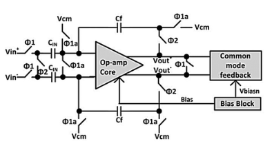
Figure 2: ADC Sample-and-Hold Circuit
In the frequency domain, sampling with any frequency fs always creates replicas of the spectrum of the original signal, centered at integer multiples of fs. In the figures below, the left-hand side polygon represents the assumed spectrum of the time-domain signal in Figure 1. Its highest frequency component is B hz, and the range [-B, B] is referred to as the baseband of the analog signal.
Periodic Sampling in the Frequency Domain

Figure 3: Spectral replication without overlap.

Figure 4: Spectral replication with overlap
The purpose of sampling an analog signal is to create a representation that can be stored and manipulated by digital computers. However, these digital representations are only valuable if they can eventually be perceived in the real world. The process of converting a sampled signal back into a continuous-time analog signal is called signal reconstruction. Depending on the relative values of B and fs, the spectral replicas created during sampling may overlap in the baseband, resulting in additive distortion. This phenomenon is termed aliasing and is perceived only on signal reconstruction.
Aliasing in the Time Domain
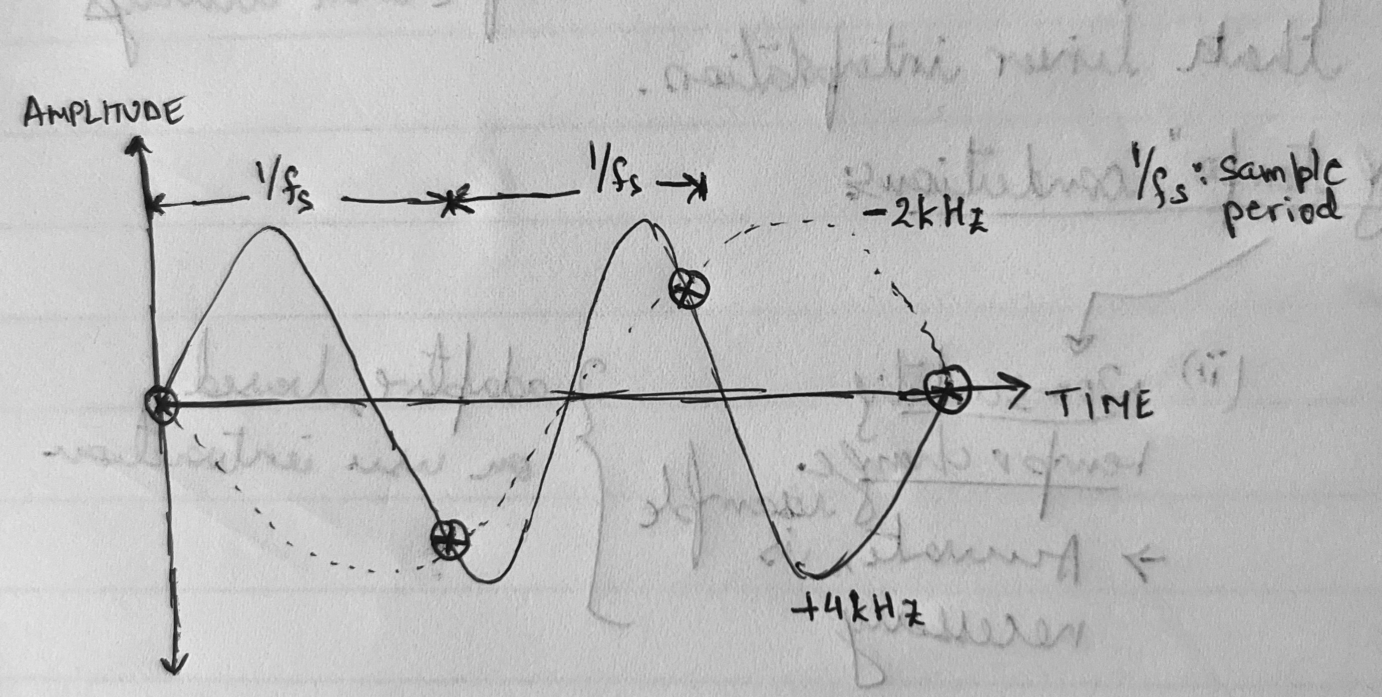
Figure 5: When a sine wave is sampled below the Nyquist rate, multiple analog sinusoids can fit the same set of samples. The figure shows two possible original signals that are consistent with the sampled data.
In theory, signal reconstruction is performed by applying an analog low-pass filter to the input sample sequence, to eliminate the spectral replications that were created during sampling. This leaves only the spectral components in the baseband. If fs > 2B as in Figure 3, the baseband spectral component after sampling still represents the original spectrum. This criterion is formalized by the Shannon-Nyquist sampling theorem, which states that an analog signal must be sampled at at least twice the frequency (called Nyquist rate) of its highest-frequency component to ensure no aliasing upon signal reconstruction.
Low Pass Filter in the Frequency Domain

Figure 6: Ideal Low pass (Brick Wall) filter, no aliasing. The reconstruction low pass filter in the DAC assumes that the input meets the Nyquist criterion.

Figure 7: Failure to meet Nyquist criterion results in aliasing.
If fs < 2B as in Figure 4, implying that the original signal has some higher-than Nyquist Rate/2 components, filtering would yield in a distorted baseband due to the "folding-back" of higher frequency sinusoid components. Therefore it is important to pass the analog signal through an analog low-pass filter before it is sampled by the ADC to restrict its frequency content.
The principle behind signal reconstruction is the continuous-time convolution process. Here, the impulse response h(t) of a First-Order Hold (FOH) filter stays stationary while the sampled sequence xflipped slides over it. While the FOH filter reconstructs an analog signal, it is clearly an approximation. In fact, the impulse response for perfect reconstruction can be derived mathematically, and it turns out to be a sinc function.
Signal Reconstruction via continuous-time convolution
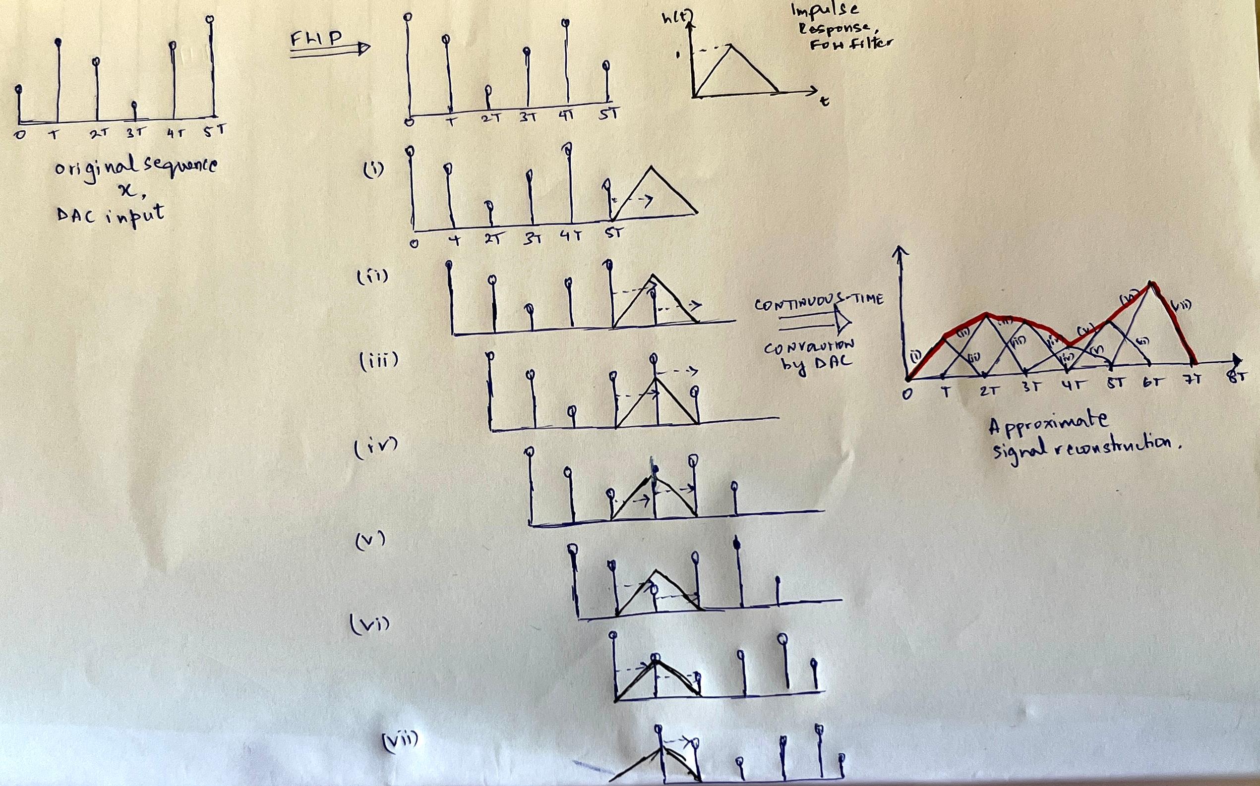
Figure 8: Convolving an input sample sequence with the continuous-time impulse response of a FOH filter. At each time step nT, (where T is the sample-period) the sample xflipped(n) scales the triangular impulse response h(t-nT). The reconstructed signal y(n) is the sum of all such shifted, scaled responses. DACs implement FOH filter in their circuits.
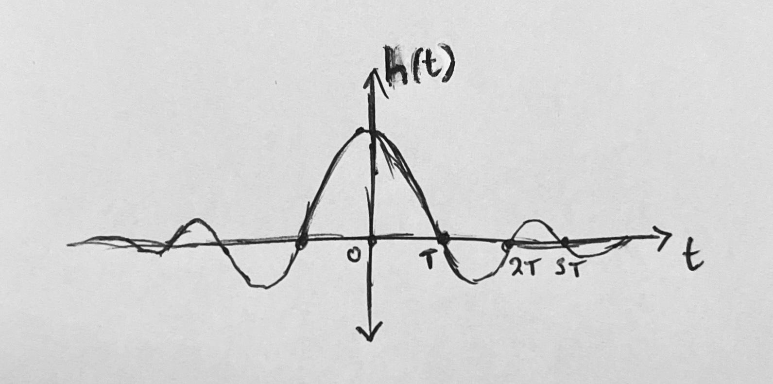
Figure 9: Sinc reconstruction kernel. In theory, convolving this function with a sample sequence implements a brick-wall filter.
To conclude:
Convolving a sample sequence with a continuous normalized sinc function is equivalent to applying a brick wall filter over its spectrum. In the time domain, this process results in reconstruction of the analog signal.
Sample Rate Conversion
It is often necessary to change the sample-rate fs of previously sampled analog audio. Re-recording from the source is quite impractical, and this has led to the development of software-based techniques to modify the sample-rate of digital audio.
Digital sample-rate conversion should be simple: Implement the DAC convolution on the digital samples to "recreate" the analog signal in software, and then implement an operation analogous to ADC sampling in software at the desired sample-rate.
The problem: Discrete-time convolution generates a discrete output sequence. While discrete-time convolution is the natural digital analogue to the continuous-time DAC convolution, its output is not continuous, and so cannot be sampled at arbitrary time instances.
Discrete-Time Convolution
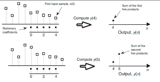
Figure 10: Convolving a 5-tap impulse response h(k) of an averaging filter with a digital signal x(nT), where T is the sample-period. Outputs y(n) are obtained by sliding the input sequence over the stationary coefficients.
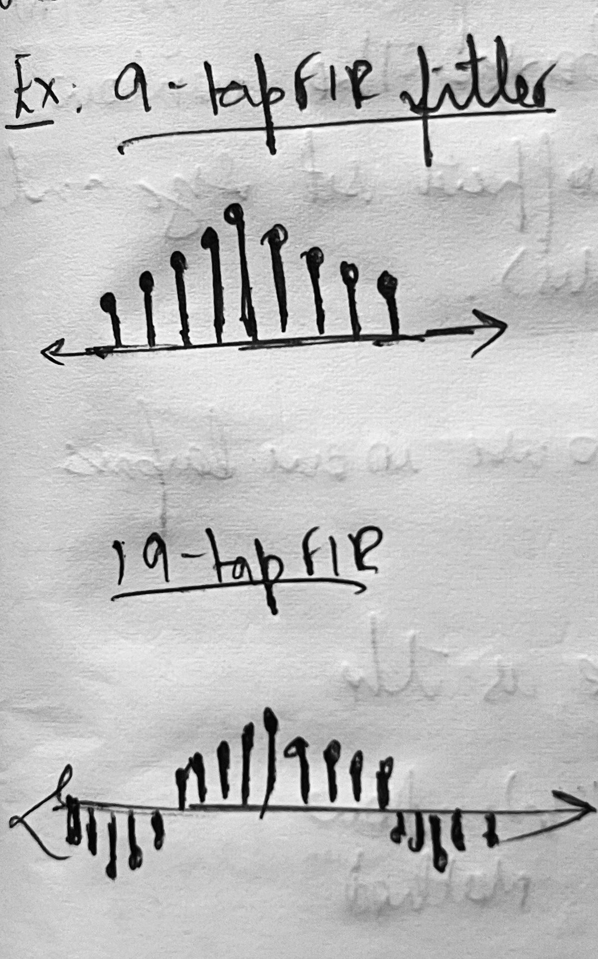
Figure 11: 9-tap and 19-tap sinc impulse responses h(k) of a lowpass filter.
The Solution: Model the original analog signal as a weighted sum of ideal, infinite, time-shifted sinc kernels, each centered on a known sample. This is effectively a snapshot of the DAC continuous-time convolution.
In theory, the continuous signal is reconstructed using an infinite number of sinc kernels:

but in practice, sinc algorithms approximate using a truncated window:

This windowed sinc interpolation algorithm can generate samples of the analog signal at arbitrary time instances. Resampling then reduces to generating a series of sample-values corresponding to a different set of time-stamps than the original. In Figure 11 below, the interpolated amplitude is the signed sum of the amplitudes of the 5 sincs at t = 0.2T.
Sinc Interpolation
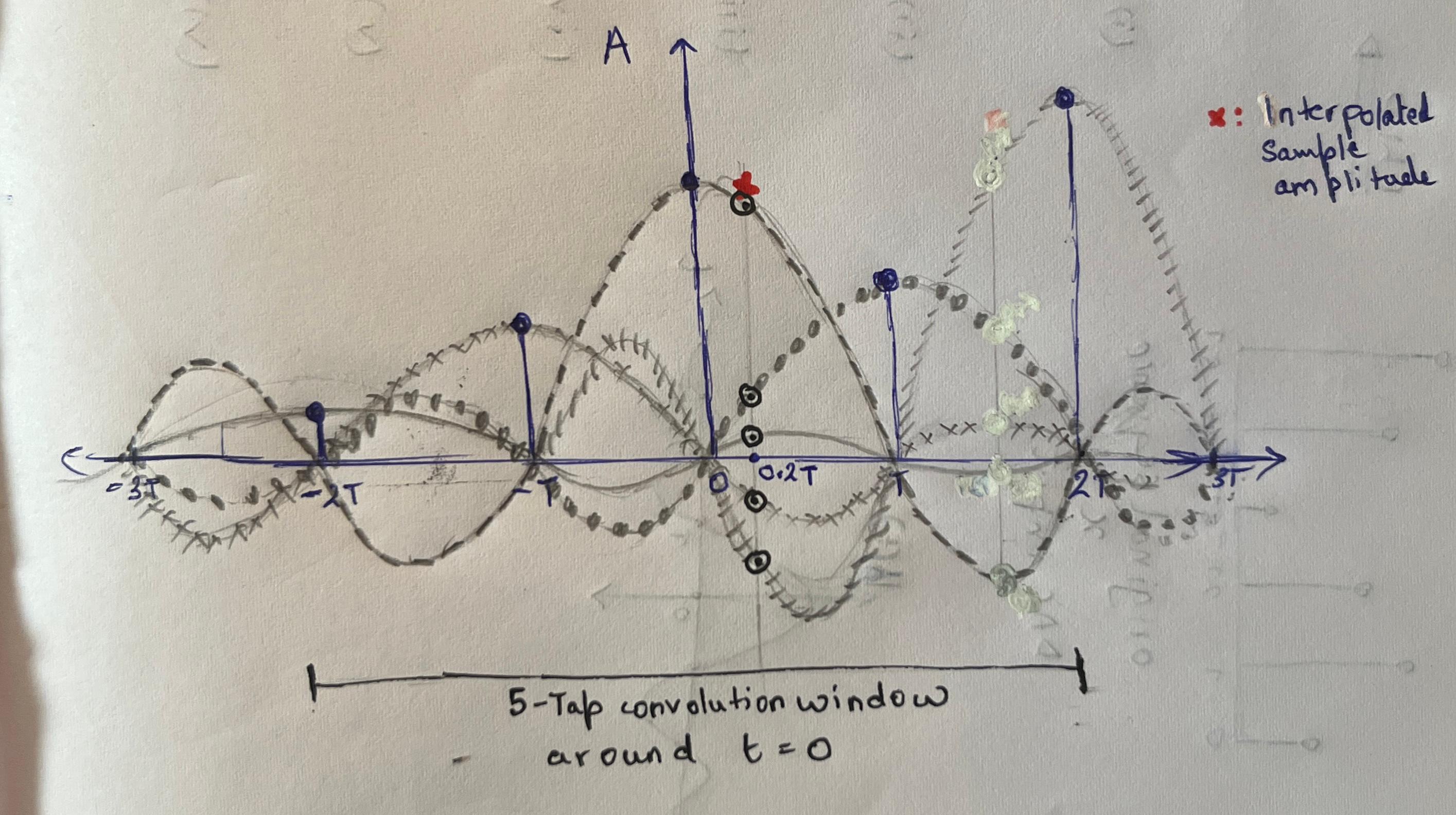
Figure 11: Resampling via sinc interplolation. Here, a N=5 tap window around t = 0 is chosen to interpolate the sample amplitude at point-of-interest t = 0.2T. Each sinc function is centered on a sample in the symmetrical size 2T window around t = 0, and scaled by its corresponding sample amplitude.
For a given point-of-interest in time:
- If the time is an exact integer multiple of the original sample period, each sinc function evaluates to zero except the one centered at that point, which evaluates to 1. This ensures that the reconstructed signal (weighted sum) perfectly matches the original sample value — there is no interference from neighboring sinc functions.
- For other, arbitrary times, the sinc interpolation algorithm first chooses the known sample at the integer multiple of the sample period closest to the point of interest. It then selects a finite set (typically N=2M+1 taps) of nearby samples, scales the corresponding sincs, and computes a sum at the point of interest.
Interpolation libraries such as libzita and libsamplerate precompute sinc values in a high-resolution lookup table of fractional sample-period offsets to speed up computations. However, these are still far more computationally expensive than a linear interpolator, which uses only two adjacent samples and computes a simple weighted average based on the fractional offset.
Audio Engineering in Practice
While the section on theoretical foundations gives important intuitions on the correctness and meaning of certain digital audio procedures, developing high-performance implementations are an engineering problem, constrained by the design of digital audio hardware and processing software.
Keywords:
Audio Encoding:
Digital computers quantize analog amplitudes using fixed-precision floats during sampling. To distribute a digital record, it is compressed (lossy or lossless) using well-known algorithms that effectively wrap the float sample-sequence in headers. MP3, WAV, AAC are some standard audio encoding formats.
Audio Frame:
Sample sequences are treated as a series of logical frames for multichannel audio. An audio frame is an array containing k copies of the current sample value, where k is the number of output channels (mono:1, stereo:2).
Audio Interface:
A gateway for audio to enter or exit a processing system. The human ear is a biological audio interface. The ADC and DAC are technological/physical audio interfaces.
Sample Rate:
For a digital record, its sample rate in Hz defines how many frames make up one second of the track. The DAC sample-rate specifies how many outbound frames must be consumed per second of real-world (wall-clock) time during playback to avoid buffer underruns. Common rates are 44.1KHz, 48Khz or 96Khz.
Audio Buffer:
Audio frames, i.e. float arrays are transported to various parts of the audio processing stack in units of audio buffers. DSP libraries often expect multi-channel audio buffers to be interleaved - i.e. each frame with k floats is placed adjacently to build the audio buffer.
Buffer Underrun:
An audio distortion that may be observed during playback. During playback, the role of audio processing software is to prepare a certain amount of frames per unit time - decided by the DAC sample-rate. Delays in preparing the required number of frames results in intervals of silence, observed as audio pops and cracks.
The Mixxx Audio-Playback Stack
The Mixxx audio playback stack consists of components in Mixxx userspace that interact with the Linux audio subsystem using the PortAudio API. PortAudio interfaces with JACK - a low-latency linux sound server that mixes audio buffers from multiple sources. This enables DJs to design more involved workflows - for example running Mixxx decks into a live effects generator before playback. JACK interfaces with the DMA-based ALSA driver in the kernel, which finally triggers audio-buffer writes from RAM to the DAC FIFO during playback.
- While JACK is essential to allow multiple real-time applications to talk to each other, a DJ performing a basic set will use Mixxx as her standalone audio source. PortAudio can also interface directly with the ALSA backend - causing Mixxx to be the sole owner of the soundcard. This provides a minor latency improvement.
The Need for Sample-Rate Conversion
Input audio must be resampled in two cases:
When there is a sample-rate mismatch between the input track and the DAC sample-rate:
While buffer underruns occur due to DAC starvation regardless of the buffer contents, this audio distortion arises when the DAC receives the wrong sequence of frames in its FIFO.
- If a 96kHz record is played back on a DAC operating at 48 kHz without resampling, only 48k input frames are processed each second—meaning less than a full second of the outbound audio is played back per second. This results in an unintended slowdown.
- Conversely, if the DAC sample rate exceeds the input sample rate, more than one second of the original recording is heard every second, creating the perception of sped-up and pitch-shifted playback.
Unintended tempo ramping
In these scenarios, resampling is a corrective procedure that transforms audio sampled at the input sampling rate to match the DAC’s expected output rate.
When there is tempo change induced by the user:
For a record sampled at 96kHz with a DAC also at 96kHz, scaling tempo by a factor of 3 means we want to pass 3x the frames to the DAC on each callback than we would during standard playback.
- Without resampling, writing 3x frames per callback in an attempt to increase tempo would overfill the Mixxx-ALSA buffers. In the worst case, the excess frames would be dropped. Either way, the DAC would still consume only 96k frames per second instead of the entire 3 * 96k — nullifying the intended tempo increase.
- For accurate tempo-ramping, we must represent a longer amount of track duration using less frames, while ensuring that there are enough remaining frames for accurate reconstruction. That is, every second, we need to represent 3 * 96k frames using 96k frames only. This corresponds to an downsample, where we decrease the number of frames per second of input audio, i.e. decrease its sample rate.
- Conversely, upsampling is used when decreasing track tempo, by increasing its sample rate. Here, interpolation is used to generate frames at non-integer multiples of the sample-period.
Mechanics of resampling in Mixxx
The Linux kernel can perform sample-rate conversion if required, using ALSA's internal resampler if necessary. Depending on kernel configuration, the resample could use linear or sinc-based interpolation provided by PipeWire or ALSA. The primary use case for such in-kernel resampling is to playback audio using aplay or ffplay via commandline.
Mixxx performs real-time manipulation of audio: live mixing, tempo changes, effects, scratching, and more. In fact, due to the low-latency requirement of these workflows, it is necessary to avoid the in-kernel resample. Therefore, Mixxx performs sample-rate conversion in userspace using a variety of external interpolation libraries.
Mixxx provides an abstract EngineBufferScale class, which is subclassed to implement resamplers using various time-stretching libraries. EngineBufferScaleST, EngineBufferScaleRubberband, EngineBufferScaleSRC, EngineBufferScaleZita implement resamplers that use the SoundTouch, Rubberband, SampleRate and libzita-resampler library APIs respectively.
During a live DJ set where the end result is an audio output, the resampling step happens in the player - between the soundsource and the engine. The exact flow is as follows, where T is the rack sample-rate and E is the Engine (DAC) sample-rate:
i. Sound source (T)
ii. Read ahead manager (T)
iii. Resample #1 (T -> E): scaleBuffer()
iv. Engine buffer (E)
v. Engine mixer (E)
With the new additions from this GSOC project, additional resampling occurs in the sidechains during recording and broadcast, where R is the recording/broadcast sample-rate:
vi. Sidechain (E)
vii. Record/Broadcast (E)
viii. Resample #2 (E -> R): scaleBufferOneShot()
ix. Encoding (R): encodeBuffer()
Emulated Vinyl Scratching
This GSOC project was derived from reports suggesting sub-par audio quality during scratching. In audio-enginieering terms, scratching simply amounts to a short-duration tempo change. As discussed in the previous section, this requires a sample-rate conversion, i.e. a resample.
A scratch can triggered by spinning the jog wheels of a MIDI controller. The architecture of Mixx ensures that the associated change in tempo ratio is made available to the resampler between DAC callbacks at the earliest. Mixxx acts on buffer chunks, for example 20 ms. The scratch control command is taken into account between these buffers. To have a steady tempo without clicks and pops, a ramp is applied. For example, if a user changes tempo from 1x to 2x, one additional buffer is used to slowly change the tempo from 1x to 2x.
The scratch control command directs the chosen resampler to adjust the quantity of input frames it requests from the Read-Ahead Manager and then interpolate to the desired output frame count. This emulates scratching - i.e. playback of high/low-frequency output due to sudden tempo change. Our empirical tests have revealed the following per-buffer resample latencies for each resampler:
| Resampler | Per-Buffer Latency |
|---|---|
| SampleRate Linear | 10 µs |
| Handcrafted Linear | 20 µs |
| SampleRate Fastest Sinc | 57 µs |
| SampleRate Highest-Quality Sinc | 448 µs |
Contributions
mixxxPR#15081: Custom samplerates setting for recording.
Status: Merged
This PR introduces an improved user experience in the recording preferences page. No more error messages for incompatible formats. The GUI maintains the necessary format+sample-rate invariants. This PR also introduces libsamplerate to the build system along with a base resampler class using the libsamplerate src_process API.
Key Files
GUI Changes

Before

After
mixxxPR#15160: Custom samplerates setting for broadcasting. Status: Unmerged
This PR allows users to choose custom samplerates for each broadcast profile, independently of the engine samplerate.
Key Files
Users can now pick custom samplerates for both recording and broadcasting, independent of the engine samplerate.
GUI Changes

Before

After
mixxxPR#15005: Support for low-latency scratching using the libsamplerate callback API Status: Unmerged
This PR implements a resampler class using the libsamplerate Callback API. We observed a reduction in per-buffer resampling latency from 20us to 10us - a 2x improvement over the handcrafted linear interpolator.
Key Files
GUI Changes

Before
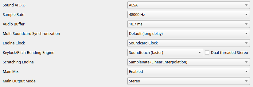
After
Future Work
- Benchmarking the latency and CPU usage of the various resamplers during scratching.
- Creating a test-suite for various scratching patterns.
Acknowledgements
I thank Daniel Schürmann, Evelynne Veys, Ronny, and Jörg Wartenberg, who have spent considerable time reviewing my PRs and offering assistance anytime I needed it.
Comments