How Does Timecode Vinyl Actually Work? (Pt. 2)
![]()
![]()
![]() serato,
timecode,
dvs,
vinyl control
serato,
timecode,
dvs,
vinyl control
In the last post, I explained how a basic relative-mode Digital Vinyl System (DVS) works. But there are two problems that are still left to solve:
- Seeking inside a track by picking up the needle from the record and dropping it somewhere else will not work.
- The basic relative-mode implementation will likely suffer from so-called sticker drift. This means that if you put a sticker on the vinyl record as visual aid and then scratch the record back and forth so that the sticker is in the same position it had before the scratch, the track should also be at the same position. If you just use the pitch information, it will likely be too inaccurate to make this work, and track position and sticker position drift apart (hence the name).
Both of these problems can be solved by throwing position information into the mix. This is why the timecode signal also contains information that can be used to detect the needle position on the record.
Getting the position out of the analog signal
From a steady sine waveform alone, it is hard to determine in which groove the needle is and at which rotation degree the platter is moving. One can imagine to count cycles of the wave from the beginning of the control track. Unfortunately this is error prone due to crackling or a skipped groove. The counted number becomes void after such an event. To restore the counted number, a periodical position information is required. For Serato timecode, this information is added to the sine wave by amplitude modulation (AM) representing the position as a series of low and high amplitudes, digital bits, where 1 is a relatively high peak, and 0 is a relatively low peak.
The right channel is just a phase-shifted version of the left one, so we only need to look at the positive peaks of the left channel.

If we look closely, we notice that the peaks occur every time the right channel crosses zero and the signal value goes from the positive part of the signal to negative part.
This is very convenient, because that way we don't have to lose any sleep over how to detect the peaks in the left channel, we just detect if there was a positive-to-negative zero crossing in the right channel, then take the current value of the left one and check if it's a 0 or 1 by comparing it with a threshold.
Now it's clear how the analog timecode signal can be converted to a stream of bits. But how can these bits be interpreted as positions? Or rather: How did the engineers that created the timecode format encode the positions as bits?
Encoding strategies
Simple Base-2 Encoding
The intuitive approach is to encode positions as a sequence of ascending numbers, e.g. the first position is 0, the second position is 1, the third position is 2, etc. Since we're working with bits, we could simply express these decimal numbers in the base-2 (binary) numeral system, like this:
| Position | Bit Sequence |
|---|---|
| 0 | 000 |
| 1 | 001 |
| 2 | 010 |
| 3 | 011 |
| 4 | 100 |
| 5 | 101 |
| 6 | 110 |
| 7 | 111 |
Of course, that is just a toy example, but even if we only had 8 different positions, we need use 3 bits (= 3 cycles) to represent each position. In reality, we want to encode a lot more different positions, which means the resulting binary number will be longer, meaning we need more bits and therefore cycles per position we want to encode.
The corresponding signal would look like this:

The first 3 cycles encode position 0, the next 3 cycles encode position 1, and so on. Simple, right? Unfortunately, this approach has a major problem.
Let's assume you seek to a random position in the track (by picking up the needle and dropping it somewhere) and the
next 3 bits are 001.
Do you know what position or cycle number we are at?
We can look up 001 in the table above and see that these bits encode position 1 (cycles 3-6).
So after reading these bits we should be at cycle 6.
And that is one possibility, but not the only one.

So there are multiple possible positions and we don't know which one is the correct one. We can mitigate this by reading the next 3 cycles too, but this doubles the amount of cycles we have to read (6 instead of 3 cycles) until we know the position for sure.
Digital Vinyl Systems need to be responsive and minimize the latency (i.e. the delay between moving the vinyl and seeing/hearing the action in the software) to be usable for scratching. Therefore, this approach is not sufficient.
The problem with the simple base-2 encoding is that may end up in the middle of a number and we don't know where a number begins or ends.
Using Sentinel Values
To detect the beginning of a new position mark reliably, we need something special, that can be clearly distinguished from the position values. Such a value is called a sentinel value and could be used to indicate "A new position value starts here".
After a seek, we have to keep reading bits until we encounter the sentinel value, then we can start reading the actual position bits. In fact, that's exactly what the early Final Scratch DVS did.
In the Final Scratch timecode, each position was prefixed by 0001, followed by 16 bit of position information.
Although using a sentinel value ensures that we know when a position starts, this approach is also problematic.
Let me explain why.
As we already stated, we want the latency between moving the needle and detecting the position to be as small as possible. Among other things, the latency is determined by how many bits we have to read until we know the position, so we want this to be as small as possible in all cases. And this is where using sentinel values fail.
Let's assume the DJ dropped the needle directly in front of a sentinel value:
 0 0 0 1 [-------16 bit position-------] 0 0 0 1 [-------16 bit position-------] 0 0 0 1 ...
^                                       ^
Needle dropped here          At this point we know the position
After reading the next 20 bits (4 bit sentinel value + 16 bit position value), we know the position. That's fine, but it's only the best case.
What if the DJ dropped the needle after the first bit of the sentinel value? That would be the worst case and we'd need to read a lot more bits before know the position:
 0 0 1 [-------16 bit position-------] 0 0 0 1 [-------16 bit position-------] 0 0 0 1 ...
^                                                                             ^
Needle dropped here                                            At this point we know the position
The DVS can't detect that the needle was dropped on the sentinel value (because the first bit is missing). Therefore, it need to wait for the next one and just ignore the remaining 3 bits of the sentinel value and the subsequent position value. Then it can detect the next sentinel value and position.
So in that case it would be necessary to read 39 bits before the position can be known. Needing so many bits to reliably detect a position is bad for latency and might make the system feel "sluggish".
Using an LFSR
It would be great if we could reduce the number of bits that we need to read to detect the position reliably - even in the worst case. In the DJ community, Serato's take on DVS is widely considered one of the best solutions. What are they using for position detection? We can get a basic idea by taking a look at the back of the Serato Control Vinyl (CV2):
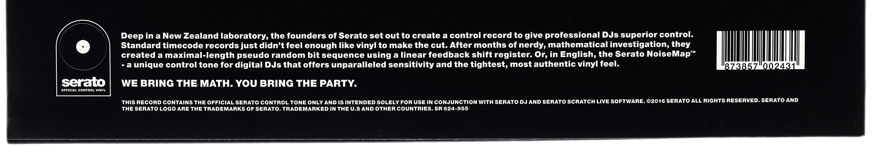
Deep in a New Zealand laboratory, the founders of Serato set out to create a control record to give professional DJs superior control. Standard timecode records just didn't feel enough like vinyl to make the cut. After months of nerdy, mathematical investigation, they created a maximal-length pseudo random bit sequence using a linear feedback shift register. Or, in English, the Serato NoiseMap™ - a unique control tone for digital DJs that offers unparalleled sensitivity and tightest, most authentic vinyl feel.
So Serato is using a Linear Feedback Shift Register (LFSR) its control signal. Sounds scary? Don't worry, it's not as complicated as it may sound.
What is an LFSR and how does it work?
A Linear Feedback Shift Register (LFSR) is a shift register that uses a linear feedback function. LFSRs are common in modern computing (e.g. for generating pseudo-random numbers), but using them for a vinyl control signal an interesting and unusual application. I'll outline the basic principle and then try to explain step-by-step using an example.
For our purposes, it suffices to know that a register is an array that contains a fixed number of bits. We are working with a Shift Register, which means means that the contents of the register are shifted to the left or right in each step.

If we shift the register's contents to the right, we need a new value that we insert at the leftmost position. LFSRs use a (linear) function that takes the current content of the register as input. The resulting value is then fed back into the register.
Let's have a look at a step-by-step example. Here's a 3-bit LFSR that generates a maximal-length pseudo random bit sequence:

In each step the following happens:
- We take the current contents of the register to calculate the feedback bit. In this case, we calculate x = s1 + s0.
- Then shift the register to the right.
- The bit that is "pushed out" of the register (i.e. the rightmost bit s0) is the output bit
- The leftmost (empty) space is filled with the feedback bit (x) we calculated.
Let's assume that the initial state of the register is (1, 0, 0).
First, we need to calculate the feedback bit x which is defined as the sum of s1 and s0.
In this step, both bits have the value 0, so x = s1 + s0 = 0 + 0 = 0
Next, we need to shift everything to the right, and insert x = 0 on the left.
The output bit is 0, because that is the rightmost bit that is "pushed out" of the register.
In the next step, the feedback bit is x = s1 + s0 = 1 + 0 = 1. Note that this time s1 has the value 1 because we shifted the register to the right in the previous step and 1 moved from s2 to s1. Now that we calculated x, we again shift the whole register to the right and write the feedback bit into the leftmost position. The output bit is 0.
We can now continue this a few more times. In step 5, the feedback bit is x = s1 + s1 = 1 + 1. Usually, the result of that calculation would be 2, but in this case it's 0. The reason for that is that we're working with bits (which are either 0 or 1), so 2 is not a valid value.
Consider a 24-hours clock: If it's 23:00 and you wait 2 hours, it's 01:00 and not 25:00. That time doesn't exist, so you just subtract 24, which is the number of possible hours from 0 to 23, to make it valid (25:00 - 24:00 = 01:00). In the same way 2 becomes 0, when you calculate 2 - 2 = 0, because 2 is not a valid bit value.
After the first 6 steps we get the following table:
| Step | s2 | s1 | s0 | Feedback bit x = s1 + s0 | Output bit x = s0 |
|---|---|---|---|---|---|
| 1. | 1 | 0 | 0 | 0 + 0 = 0 | 0 |
| 2. | 0 | 1 | 0 | 1 + 0 = 1 | 0 |
| 3. | 1 | 0 | 1 | 0 + 1 = 1 | 1 |
| 4. | 1 | 1 | 0 | 1 + 0 = 1 | 0 |
| 5. | 0 | 1 | 1 | 1 + 1 = 0 (mod 2) | 1 |
| 6. | 0 | 0 | 1 | 0 + 1 = 1 | 1 |
In the next step, we would insert the feedback bit (1) at the leftmost position and shift the other bits to the right, which results in the state (1, 0, 0), which is exactly the state we started with. From now on, the table rows would just repeat forever.
This means that this LFSR has a period of 7 (because it repeats after 7 steps). That is the maximal period length you can archieve with a 3-bit LFSR.
Other 3-bit LFSRs that have a shorter period length exist, e.g. if you have an LFSR where the feedback bit is calculated as x = s0 it will already repeats after 3 steps, no 3-bit LFSR will have a longer period.
Hence, we now know how to generate a "maximal-length pseudo random bit sequence using a linear feedback shift register" just like Serato has. Let's check how that can be used to solve the problem at hand.
LFSR output as timecode signal
In each step of the LFSR example above, we get exactly one output bit (the rightmost bit of the LFSR that is "pushed out"). The example has six steps, thus we also get 6 output bits:
0 0 1 0 1 1
Since the LFSR has an internal state of 3 bits, we can use 3 subsequent bits for encoding positions, like this:
| Position | Bit Sequence |
|---|---|
| 0 | 001___ |
| 1 | _010__ |
| 2 | __101_ |
| 3 | ___011 |
The corresponding timecode signal would look like this:

We can now observe an interesting property of our 3-bit-LFSR-based output signal: Any sequence of 3 bits in the signal is unique.
This is great and exactly what we want, because after reading 3 bits we now know unambiguously which one of the 4 positions we're at.
How big does the LFSR need to be?
The example above is obviously a toy example. In real life, we want to a lot more than 4 different positions.
The Serato Control CD has a play time of approximately 16 minutes 20 seconds, or 16 * 60 + 20 = 980 seconds. At a timecode frequency of 1000 Hz (cycles per second), we have 980,000 cycles. Every cycle encodes one bit, therefore we need an LFSR with an output length of at least 980,000 bits before it starts to repeat.
At most, an n-bit LFSR can output 2n - 1 bits before it starts to repeat. An LFSR with such a period size is called a maximal-length LFSR, and we already mentioned that Serato states that it uses a such an LFSR on the packaging of its timecode media.
The smallest possible LFSR that can output at least 980,000 bits without starting to repeat needs at least 20 bits of state. A 19-bit LFSR is too small, because 219 - 1 = 524,287 is less than 980,000, but a 20-bit LFSR can output up to 1048575 bits before it starts to repeat. We don't want to make the LFSR larger than absolutely necessary, because the larger the register, the more bits we need to read before we can detect a position after a needle drop. Hence, increasing the LFSR's size also increases the latency.
A Real Life Example
Let's have a look at a real-life DVS that relies on an LFSR for position detection. We already know that Serato's timecodes uses an LFSR, but what does it look like exactly?
Fortunately, we can find out by using the Berlekamp-Massey algorithm. It takes the bit sequence decoded from Serato's timecode, and finds the shortest LFSR that produces that output.
For the Serato Timecode CD bit sequence, the algorithm finds the following LFSR:

We also have to find the correct seed (initial bit state for the LFSR), but this is trivial:
We know the first 20 bits of the timecode (e.g. by simply looking at the waveform) and we also know that this bit sequence is unique. First, we select a random non-zero bit sequence as initial LFSR state and then step through the LFSR states while comparing the output of the LFSR with these first 20 bits of timecode bit sequence. As soon as we see these 20 bits, we just go back 20 steps to the LFSR state before the first bit of that sequence appeared in the output. This is the seed.
A DVS could now generate a lookup table (LUT) that maps each LFSR state to a position. When reading bits from the timecode, it can then perform a simple lookup to get the corresponding position.
Increasing the signal frequency
Another way to reduce the latency is to increase the signal frequency. Serato uses a signal frequency of 1000 Hz, Final Scratch uses 1200 Hz and Traktor Scratch MK2 even uses 2000 Hz. This means that if you play the record at its original tempo, Serato will read 1000 bits in a single second, Final Scratch will read 1200 bits and Traktor Scratch MK2 can read 2000 bits. Sound like a good way to reduce the latency, right?
Unfortunately, a higher signal frequency also comes with a cost: The signal's maximum frequency must not exceed half the sampling frequency, otherwise signal folding will occur and lead to information loss. If you use an audio interface with a 44100 Hz sampling frequency (or sample rate), the signal's maximum frequency at which is can be sampled losslessly (called Nyquist frequency) is 22050 Hz.
When DJs scratch using DVS, the record is being moved back and forth very fast, so it's not played back at the original speed. If they move it too fast, signal folding will lead to misdetection of the bits. With Serato, you can speed up the record up to 22.05 times of the original speed before that happens. Traktor MK2 only allows a scratching speed of 11.025 times before the Nyquist frequency is reached and signal folding occurs.
Hence, the signal frequency is a tradeoff between latency (how many bits per second) and maximum possible scratching speed.
Conclusion
I hope these two blog posts were interesting and helped understanding how DVS works internally. Of course, this was just a basic introduction, and there's still more to consider, like dealing with noise, dusty vinyl, etc. And the information read from the timecode vinyl still has to be hooked up to the GUI and audio engine of the DJ software, which is challenging on it's own.
If you want to see an actual DVS implementation, check out Mark Hills' excellent free and open-source xwax software. Its timecode decoder is what Mixxx uses internally to provide vinyl control.
You can also have a look at vinylla, a toy library that I started to get a better understanding of DVS (and also to learn how to program in Rust).
And if you want to help improve the way Mixxx' DVS capabilities or want work on other parts of Mixxx, hit us up on Zulip Chat!

Comments